Over the last few weeks I’ve had the privilege to assist SLW over at DIY Effects on a new PCB offering. It’s a FuzzFace circuit that has many great features:
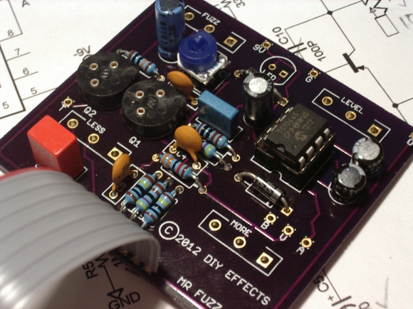
- A nice quiet power supply section that offers positive and negative ground. You simply place a jumper where you need it to be. Firstly this means you can use NPN and PNP depending on your set of transistors. Secondly with the recommended transistor sockets, (and the jumper sockets I added) you can switch between silicon/germanium or NPN/PNP in about 30 seconds. (See the ‘B’, ‘V’ and ‘A’ holes on the partially assembled picture below).
- It has options for a couple of caps that can help reduce hum and soften the distortion a little. These are part of the Fuller Mods.
- It has options for the other Fuller Mods; namely the ‘Less ‘ and ‘More’ pots. ‘Less’ or what I decided to call ‘Load’ (even though SLW nor I can decide on what to call it) acts upon the input. The ‘More’ control plays with the voltage on the top of the second transistor, which in effect changes the bias. This will tweak the waveform distortion characteristics. In fact, SLW prefers to call this control “Bias”, because that’s exactly what it is. More on this later.
- The PCB features a spot for an optional trimmer to aid in deciding where the ‘Bias’ pot ‘centers’. More on this later.
- The PCB has been designed to use DIY Effects ‘stmp’ switch and ribbon combo. This makes the wiring of the off-board stomp 3PDT switch a 30 second job. We’ve all spent much longer than that cutting and stripping 9 wires to wire one up normally, so this is a godsend.
- The other time-consuming (and error-prone) part of wiring a stomp box is the potentiometers. The DIY Effects fuzz PCB has holes setup so that you can use PCB style Alpha pots instead of the regular lug type. Again this significantly speeds up the assembly of the board. And it gives you a very sturdy board support within the enclosure, so no need for dodgy nylon supports anymore. Of course if you want to use wires, you still can.
- The PCB is designed to fit neatly into a 125B sized enclosure.
Choices to make
There’s no shortage of voodoo going around about the FuzzFace circuit; mostly surrounding which transistors to use. Some say that germanium is the only way to go, but it seems that’s more an artifact of the times rather than through any real objective truth. Jimi Hendrix was using germanium FF boxes because that’s all there was at the time (probably). The likes of Eric Johnson (or any modern hipster indie guitarist playing a Mosrite) is probably using a silicon transistor based FF. The reason being, germanium transistors are unstable depending on temperature, and they vary widely in terms of gain and leakage from one to the next. The industry switched to silicon precisely to combat this problem. So this is yet another case of a manufacturer using whatever they had on had at the time, not because of some kind of mojo.
Despite all this superstition, which normally sends me running, I went for a pair of AC128 germanium transistors from Mammoth Electronics. A pair of germanium transistors can cost anywhere between $10 and $50 depending on how much you’re prepared to be fooled; either way they’re orders of magnitude more expensive than their silicon counterparts. So choice one: AC128 transistors. This means I must use positive ground when I wire everything up. Make a note.
I also chose to try all the Fuller Mods. This was mostly because I hadn’t ever used a Fuzz-face before, so was eager to try it in all it’s ancient and modern glory. As a nod toward what might be called the mediocre standard circuit, I did initially build a completely standard silicon fuzz. This proved encouraging, so I ploughed on. Geofex has a fantastic discussion on The Technology of the Fuzzface (including the Fuller Mods).
Decals
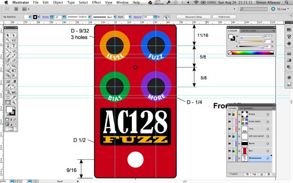
This is often the most stressful, but ultimately satisfying part. I was able to designing something with much greater confidence this time as I started with a drilling guide supplied by DIY Effects. It was PDF form, and layed out accurate to the millimeter. This meant not only did I have a perfect basis for my design itself, but I could design it over the spots for the holes that I would then use for a drilling guide. Adobe Illustrator was my software of choice. Inkscape wasn’t working out as you cannot zero the ruler arbitrarily, which irritated me to no end.
Assembly
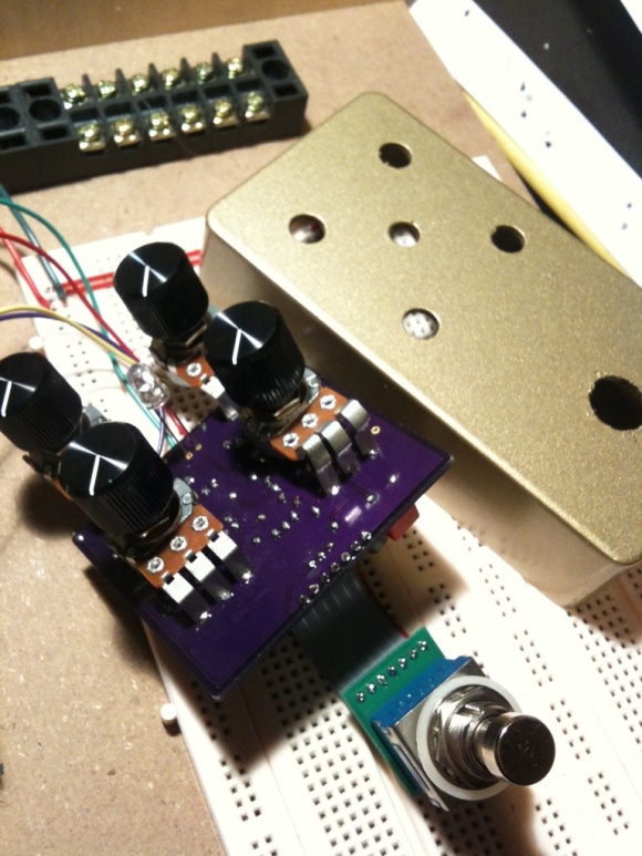
Initially I made a huge mistake in ordering a 1590B enclosure instead of the correct 125B size. This mean I went ahead and drilled the holes and even sprayed the enclosure a lurid gold metallic. When I came to test the layout by offering up the board it didn’t fit…at all. But that’s OK. I will use the gold enclosure for an eventual silicon fuzz. 5 minutes on the Mammoth site and I had ordered the correct enclosure with a lovely Tiger Red sparkle finish.
NOTE: It’s hard to see from the above picture, but there are only 4 wires coming off this finished board; signal in/out, 9V in and ground. With the new ‘stmp’ board and SLW’s choice of potentiometer, this is all you have to then wire into the enclosure. It’s magical!
Biasing and Temperature
As mentioned in the preamble, the fully featured PCB has a Bias control, and a trimmer. The Bias control is able to swing the bias on Q2 across an approximate range of 3 volts.
The typical FF circuit is setup to have -4.5v (measured at point ‘T’ on the PCB). The Bias knob allows you to swing that up to as much as -5.0v. The trimmer will allow you to decide the start of this range of adjustment.
While tinkering with these two controls I happened upon a characteristic of germanium transistors. i.e. they are sensitive to temperature. Now after reading plenty of articles about FF circuits I knew this, but I didn’t really understand what it meant. I had imagined that it meant their “performance” in a circuit might be thrown off by say 50%; much like the way most reasonably priced passive components have tolerances. What I wasn’t expecting was what I observed first hand. When I was tweaking the trimmer to adjust the range of the bias I had the unit on its back with the bottom plate off, and my left hand held the red multimeter probe on lug T. My right hand held the screwdriver placed on the trimmer. My multimeter sat behind the unit so I was forced to lean in close to see it. When I started to make the adjustment the first time, the bias voltage leaped up to about -6.5v!!
This caused me to replace R2 with different values, but that made no difference. And indeed I was getting what amounted to random bias ranges with each change. At this point I became frustrated and stopped for a while. When tempers cooled I came back to it, and measured the bias again…it had dropped back to around -5v and I could move it back towards -4.5v with the trimmer. But then as I did just that it started to rise again. I checked for the seating of the transistors in their little sockets, but they seemed firm. Then it hit me…temperature! I placed a finger on top of the transistors and sure enough, the voltage went nuts. It was being affected by me breathing on it while I was making adjustments.
So at this point I returned the circuit to standard values, set the bias for -4.5v (with the ability to go up to -5.0v using the bias knob) and called it a day. A very instructive waste of time 🙂
The finished article
Once the decal had dried, and the clear coats had been sprayed, I waited 3-4 hours for the paint to dry. The last couple of pedals I finished myself I had used Krylon clear coat. It works well, but it sprays on very, very thick, and literally takes weeks to dry sufficiently. Until that point it is prone to finger prints and other such handling artifacts. For the Fuzz I tried Rustoleum clear gloss. It sprayed on about the same as the Krylon, although it was less forgiving and I had to be careful to keep it “wet” but not by too much. Also, due to my impatience I was spraying in high humidity, so it tended to go on cloudy (moisture in the air), but cleared soon after. But anyway, all turned out well, so here’s the finished pedal:
A quick demo MP3 file of the DIY Effects Fuzz Circuit:


